Porsche Cayenne S (955) Rear Wheel Bearing Replacement June 24 2021
There was a faint whirring sound coming from the rear of our Cayenne, so it was time to replace the rear wheel bearings. I typically love working on cars, but I gotta be honest that this was quite a brutal job. There are gigantic bolts with high torque values, finicky parking brake parts, control arms that fight with you as you try to wrestle them back into place, and awkward part geometry that makes putting the parts in a shop press difficult.
This job is not recommended for beginners, and this DIY guide assumes that you know how to work on vehicles safely and operate a shop press safely. If you're up for the challenge, let's get started. The right, rear wheel bearing is what we will be showing. We have to have the car on the ground with the center cap removed from the wheel so we can loosen the axle nut. Before we lift the vehicle, we need to disable the auto leveling feature.

With the key in the ignition and turned until the dash lights up, hold the toggle lever forward for approximately 5 seconds until the dash board indicates that regulation has been turned off. Also, make sure the parking brake is on, and the front wheels chocked.
We jack up the car, put it on jack stands, remove the wheel in question and tap out the center cap from the inboard side. We used the handle of a mallet to tap the center cap out.

With the center cap off, put the wheel back on, torque the lug nuts and lower the car back down. You may be wondering why this is necessary. We are going to be applying a large amount of torque to the axle, and we don't want the drive train reacting this huge torque, but rather the wheels and parking brake, which can handle these large torques.
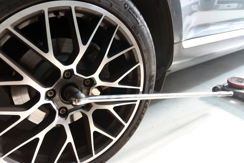
Use a large breaker bar and a 32mm 12-point socket to loosen a few turns, but do not remove the axle nut. The axle nut is a standard right-hand thread nut. We used a 38 inch breaker bar with a 3/4 inch drive. In the past, we've tried using a 24 inch breaker bar with a 1/2 inch drive, and it was insufficient. It was flexing too much and was going to break before the axle nut was going to budge.
Now, we are going to jack the car back in the air, and remove the wheel. The next phase is to strip the brakes and miscellaneous sensors off of the wheel carrier.
Tip: This is a messy job because of brake dust, and covering the floor with cardboard, plastic sheeting or a disposable cloth is not a bad idea. I also recommend wearing a respirator, because you will likely breathe in some brake dust if you don't.

Unfasten the mounting bracket on the inboard side of the caliper that holds the brake hose. This gets in the way of removing the caliper mounting bolts, so it has to come out.

Undo the 2 brake caliper mounting bolts. These are M16 triple-square bolts, NOT Torx bolts.

Don't let the brake caliper hang from the brake lines. You may bend and weaken the brake lines if you do this. Typically, we use a stiff wire or rope to suspend the brake caliper, but the lower control arm acted as a convenient shelf to store the brake caliper on.

Disconnect the wheel speed sensor harness. Unbolt the bracket holding the sensor harness. This bracket is hard to photograph and hard to see because it is tucked away on the top of the wheel carrier on the inboard side.

Remove the T50 Torx bolt holding the brake rotor to the hub. Next, we will have to disengage the parking brake to release the brake rotor, but before this, it is important to double check the chocks on the front wheels. If they are correctly in position, proceed to disengage the parking brake.

Remove the brake rotor. Sometimes there is some corrosion holding the rotor onto the hub. A few smacks from a rubber mallet loosens it up, and if that doesn't work, escalate to an engineer's hammer or mini sledge hammer. Be mindful that whacking your brake rotors hard enough can cause them to crack, so use the minimum amount of impact necessary. Also, wear safety glasses any time you're hitting metal with a metal hammer.

Now we have to remove the parking brake assembly so that the parking brake cable can be free of the wheel carrier, and we can take our wheel carrier to the shop press. Turn the adjustment knob until it is in the slackest position. We used a flathead screwdriver leveraged against the hub to turn the knob.

Remove the 2 screws holding the brake shoes to the dust shield. These are quarter-turn fasteners. Just push them in, turn them 90 degrees in either direction, release them and they should pop out.

Unhook the springs holding the two brake shoes together. These springs are pretty strong. A pair of needle nose pliers were insufficient. We used some Channellock pliers instead.

Remove the entire parking brake assembly. Note the orientation of all the parts.

We have to remove the parking brake cable from the wheel carrier. Undo the snap ring on the back of the parking brake cable, and pull back the protective sleeve.

Our parking brake cable didn't come out easily, so we had to wiggle it out with vise grips.

Now remove the axle nut completely and drive the axle inboard until it falls out of the wheel hub. A center punch and a mini sledge hammer got the job done. The wheel carrier is now free from everything except the 5 mounting points from the control arms.

There are 5 mounting points that have to be disconnected. I removed them in the order shown. Note in the photo how bolt 2 can't be removed before bolt 1 is removed. Bolt 4 is not visible in this photo, but it goes to the front, lower control arm.

It helps to label and organize the fasteners for easy re-installation. Note that all the bolt heads are on the aft side and all the nuts are on the forward side.

With the wheel carrier free, we can now remove the parts that require a press to remove. But before starting, I recommend removing the blue wheel speed sensor so that it doesn't accidentally get damaged. We placed a few bars of 1x3 inch .063" wall rectangular tubing across the wheel carrier to support it. We used a socket slightly smaller than the diameter of the hub to press out the hub... only the steel tubes bent before the hub budged. We had to try something else. You might have better luck with solid steel bars or at least thicker walled tubing. A short cylinder made of thick-walled pipe slightly larger than the hub might have worked as a support, but we didn't have any pipe that large.

We put a large bearing separator on the hub, and then we put the wheel bolts through the hub. We snugged down each of the bolts and then proceeded to tighten each bolt 1/3 turn at a time. The hub will click and pop as it slowly works it's way out. Eventually, the threads of the bolt will bottom out on the hub. You'll have to back the bolts out, put some scrap metal in between the now-larger gap between the bearing separator and hub and continue as before. This process takes a long time. If you can get the gap large enough, you can take the assembly back to the press and fit some beefier bars than before.

This is a jig that I had welded up. It is made of 2x2 inch, 1/4" wall steel tubing. There are a couple of removable vertical supports that help support things. This jig along with some penetrating oil did the trick, but it was close to maxing out our 20-ton shop press.

The old bearing almost always splits apart when the hub is forced out, and this was no exception. One of the outer races was stuck to the hub. We need to remove everything off the hub so we can press the hub back into the new bearing. We took our large bearing separator and with our press, separated the race from the hub.

Here is the hub separated from the bearing race.

We turned our attention back to the wheel carrier. There is a large snap ring on the outboard side of the wheel carrier that keeps the wheel bearing from coming out. Remove it with a set of large snap-ring pliers, a large pair of angled needlenose pliers, or pry them out with a couple of screwdrivers. We used a pair of large angled needlenose pliers with the noses ground down slightly to fit into the snap-ring holes.

With the snap-ring removed, we pressed out the bearing toward the outboard side of the wheel carrier. We placed a large disc (not shown) from our wheel bearing kit in between the bearing and the shop press ram. Our jig worked like a champ.

This next step is VERY IMPORTANT! One side of the wheel bearing is magnetized. This is so the wheel speed sensor can measure the rpm of the wheel. We need the magnetized side of the wheel bearing on the inboard side where the blue wheel speed sensor is. If you get this wrong, your ABS and traction control systems will not function and you will likely receive fault messages. Use a paperclip or other small piece of steel to verify which side is magnetic. I recommend against using a screwdriver because some screwdrivers are magnetic, which can damage the magnetism of the wheel bearing or give you a false positive for magnetism.

We set up our wheel carrier to press in our new bearing. We used a cylinder from our wheel bearing kit to support the wheel bearing. You can't see it in the next photo, but you can tell that something is there, supporting the wheel carrier.

We pressed in the new bearing, using a disc from our wheel bearing kit. We pressed until the bearing was flush, but the bearing still has a little further to go. I must stress that it is important not to put any forces on the bearing that will separate the inner race from the outer race. If you are squeezing the outer race into the wheel carrier, don't apply force only to the inner race.

To press the bearing all the way in, we took the old bearing and ground down the outer diameter a bit. If you don't grind off enough, the old bearing will get stuck in the wheel carrier. We put the old bearing over the new bearing and pressed the new bearing in the rest of the way until it bottomed out. Using the outer race from the old bearing ensures that we are only pressing on the outer race of the new bearing.

Pop a new snap-ring into place to keep your wheel bearing secure. It is highly recommended to use a new snap-ring, as pressing out the hub usually damages the old snap-ring.

We are now ready to install the dust shield and press the hub in. Make sure the dust shield is flipped the right way. The dust shield is shown installed incorrectly in the photo. The lip on the outer perimeter should point outboard, helping to surround the brake disk just a little more. To press in the hub, we will need to support the inner race of the bearing from the bottom. We used a section of pipe that was approximately the same size as the inner race.

With the hub pressed back into place, putting everything back together is the reverse of disassembly. The exception is the parking brake, which has a couple of tricky items. The springs that hold the 2 shoes together are quite strong. It takes about 100 pounds of force to open them up enough to fit them back in place. After trying pliers and prying with screwdrivers, I improvised a tool out of a short piece of square tubing and some baling wire. By stepping on the square tubing and using pliers to guide the spring into the hole, I was able to get the spring back in.
The other tricky thing about the parking brake is adjusting it properly. You want to find the adjustment where the brake shoes drag on the rotor, and then loosen the adjustment 1 click. I did this by fitting the brake rotor, and making sure it was fully seated on the hub with the parking brake adjustment access hole screw removed. I positioned the parking brake adjustment access hole in front of the parking brake adjuster. I then tried rotating the brake rotor. If it rotated freely, I reached into the access hole with a flathead screwdriver and tightened the parking brake adjuster 1 click and tried again. I did this until the brake shoes were dragging on the rotor, and then I loosened the adjuster 1 click.
The rest is mostly just reattaching the control arms and mounting the brakes. It does help to have an assistant wrestle the arms into position while you try to stick a bolt through the connection. A rubber mallet and a pry bar can help to persuade the parts into alignment. I didn't have an assistant, but I had to use advanced techniques like wrestling the parts into alignment with my 2 hands, and then using my foot to push the bolt through.
With the wheel back on the ground and the parking brake engaged, torque the axle nut to 340 ft/lbs. If you finished the job, I offer you my congratulations. This is not an easy job, and you should feel a sense of satisfaction for a job well done!
Related Articles:

Porsche 955 Cayenne Front Wheel Bearing Replacement
